
Game Boy Hardware Explained, Part 3: The Screen

Updated: 18 hours ago
Hold an original Game Boy in a bright room and the first thing you notice is the window: a small, calm, olive-green rectangle sitting behind a plastic lens. It is the part everyone remembers, and the part that gave the machine its official name. The letters DMG stamped on the board and printed on the box stand for "Dot Matrix Game", a reference not to the processor or the cartridges, but to this screen and the grid of dots it is built from. This part of the series is all about that window: what kind of display it is, why it glows green rather than grey, why it needs daylight to work, and why so many of these screens develop the same faults thirty years on.
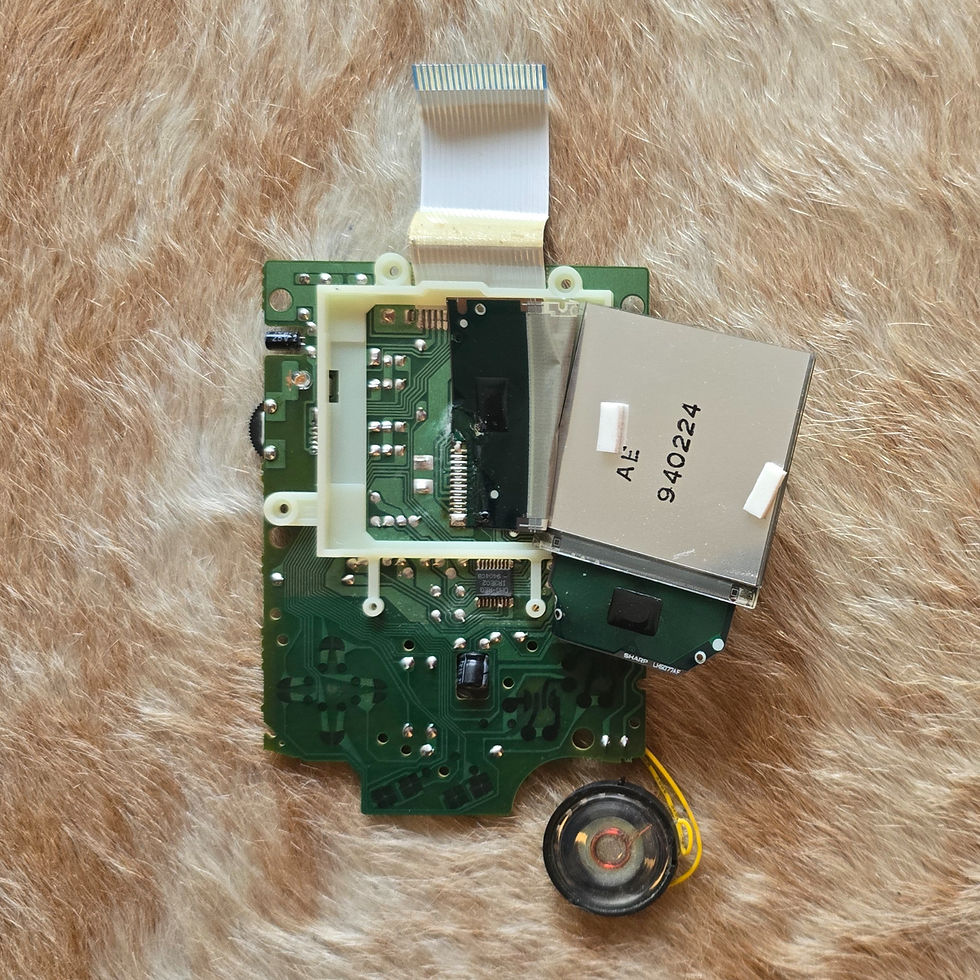
The annotated board below maps out every part of the display we are about to walk through, from the LCD glass itself to the ribbon cable that carries the picture back to the main board.

A screen with no light of its own
The Game Boy screen is a reflective liquid-crystal display, and the word reflective is the key to understanding almost everything about it. A modern phone screen makes its own light and shines it at your eyes. The Game Boy screen does the opposite: it has no lamp behind it at all. Instead it relies entirely on light from the room bouncing into the glass, passing through the liquid-crystal layer and reflecting back off a mirror-like surface at the rear. The liquid crystal does not create brightness; it simply decides, dot by dot, how much of that borrowed light is allowed to return to your eye.
This is why the Game Boy is wonderful in sunlight and useless in the dark. With no ambient light there is nothing for the screen to reflect, so the picture simply vanishes. Nintendo chose this design on purpose. A reflective screen draws almost no power, and battery life was everything for a machine meant to live in a coat pocket and run on ordinary AA cells. The trade-off (needing good lighting) was accepted, and it created an entire cottage industry of accessories: clip-on lamps, magnifying lenses and the licensed Nintendo light-and-magnifier units that a generation used under the bedsheets after lights-out.
One hundred and sixty by one hundred and forty-four dots
Behind the lens, the picture is a grid of 160 dots across and 144 dots down, just over 23,000 pixels in total. By today's standards that is almost nothing; a single modern icon uses more. But the whole machine was engineered around exactly this number.
Graphics on the Game Boy are built from small 8-by-8 tiles, and a 160 by 144 screen is precisely 20 tiles wide and 18 tiles tall, which is why game artists thought in tiles rather than pixels. The dots are square and clearly visible, and that visible grid, the dot matrix, is not a flaw but the display's defining look.
The screen redraws itself around sixty times a second, close to 60 Hz, and the console's whole sense of timing is tied to that rhythm. Programmers learned to do their most delicate work in the brief pause after the screen finished drawing one frame and before it began the next, a gap known as the vertical blank. Get the timing right and the picture was rock-steady; get it wrong and the image tore or flickered.

The two chips that scan the screen
A grid of pixels cannot light itself. Something has to sweep across the screen, deciding dot by dot what is dark and what is clear, fast enough that your eye sees one steady picture. On the Game Boy that work is shared by two dedicated LCD driver chips, and you can pick them out on the hardware as the parts marked 4071 and 4070.

They split the job by direction. One is the column driver, often called the X driver: it rides on the display's own flexible strip, the chip marked 4071, and it looks after the 160 columns of dots running across the screen. The other is the row driver, or Y driver, marked 4070 and mounted on the LCD board itself, and it steps down the 144 rows one after another.

The LCD controller built into the main processor (described in Part 2) streams the picture to this pair, and together they convert that stream into the exact voltages that switch each dot: the row driver selects one line, the column driver fills in all 160 dots along it, and the two march down the screen around sixty times a second to paint a full frame. No dot has a transistor of its own, the way it would on a modern active-matrix panel, which is part of why the picture is so cheap to drive and also why it responds so gently.
Four shades that were never really grey
Each dot on the Game Boy can be one of four shades, and only four. In computing terms that is two bits per pixel: black, dark, light and white, with nothing in between. Developers used those four tones with enormous care, leaning on dithering (chequerboard patterns of light and dark dots) to fake extra shading that the hardware could not truly produce.
People often call them four shades of grey, but anyone who has held an original DMG knows they are not grey at all. The reflective panel has a distinctly green, almost olive or “pea-soup” tint, a by-product of the particular liquid-crystal and polarising layers Nintendo used. That green cast became part of the console's personality. It is also one of the clearest ways to tell the original apart from the later Game Boy Pocket, whose screen moved much closer to true black-and-white.
The contrast wheel and the voltage behind it
On the left edge of the console sits a small thumb-wheel marked contrast. It is not decoration. A liquid-crystal display needs a carefully set voltage to twist its crystals by just the right amount, and the ideal setting drifts with temperature: the screen looks faint on a cold morning and dark on a hot afternoon. The wheel lets you trim that voltage by hand until the picture looks right.
What makes this interesting is that the screen needs a voltage the batteries alone cannot provide: a small negative bias voltage, more negative than the battery's zero reference. The console generates it internally with a dedicated circuit that pumps and inverts the supply, and the contrast wheel simply adjusts the result. So the humble dial on the side is the visible end of a quiet little power-conversion circuit working behind the plastic. Power is the subject of its own part later in the series; here it is enough to know the screen is a fussy component that demands a voltage of its own.
Ghosting, and the games that embraced it
The liquid crystal in the Game Boy is slow. When a dot switches from light to dark it does not snap across instantly; it fades over several frames. On a still screen you never notice, but the moment something moves quickly you see ghosting: a smeary trail following fast objects, as the dots lag behind the action.
Rather than fight this, the best developers worked with it. Flickering was used as a trick: a sprite drawn only every second frame looked semi-transparent to the eye, letting the machine fake effects it could not otherwise manage, and letting games show more objects than the hardware was strictly meant to handle at once. The screen's weaknesses, in other words, quietly shaped the way Game Boy games were designed and the way they look.
The ribbon, the glass and the missing lines
The display itself is a sealed sandwich of two glass sheets with liquid crystal and polarising film between them. It connects out through a thin flexible ribbon, and the join between the glass and that ribbon is made not with solder but with a heat-bonded conductive strip: a band of adhesive packed with tiny conductive particles that carry the signals across the gap.
That bond is the screen's weak point, and it is behind the single most famous Game Boy fault: missing lines. As the adhesive ages and the console is knocked about, the connection to one or more rows or columns of dots fails, and a blank line appears straight across the picture. It is so common that fixing it is almost a rite of passage among restorers, who gently reheat the strip to reflow the bond and bring the dead line back to life. A second age-related problem is the polarising film, which can bubble, cloud or peel over the decades. Both faults are reminders that this screen is a piece of 1980s chemistry, not a modern panel, and that keeping these green windows alive is a real part of preserving the machines.
For all its limits (no light of its own, four greenish shades, a tendency to ghost and to lose lines with age) this little reflective screen is what made the Game Boy portable in the first place, and it is the feature people picture the instant the console is mentioned.
Specifications at a glance
Property | Specification |
|---|---|
Display type | Reflective STN LCD, passive matrix |
Backlight | None (needs ambient light) |
Screen size | 2.6 in (66 mm) diagonal |
Resolution | 160 x 144 pixels |
Tile grid | 20 x 18 tiles (8 x 8 px each) |
Shades | 4 (2 bits per pixel) |
Refresh rate | 59.73 Hz |
Tint | Greenish / olive |
Column driver (X) | Chip marked 4071, on the display flex |
Row driver (Y) | Chip marked 4070, on the LCD board |
Contrast | Manual wheel; uses a negative bias voltage |
Common fault | Missing lines (glass-to-flex bond) |
The Series
Overview · Part 1: The Shell, Buttons and Controls · Part 2: The Main Board and the Sharp Processor · Part 3: The Screen (you are here) · Part 4: Sound · Part 5: Power · Part 6: Connectivity and the Link Port



Comments