
Game Boy Hardware Explained, Part 2: The Main Board and the Sharp Processor

Updated: 18 hours ago
If the shell in Part 1 was the body, the main board is the brain and nervous system. Lift the plastic shell off and you are looking at the single green circuit board that makes the Game Boy a computer: a processor, its memory, a quartz heartbeat, and the connections out to the cartridge, the screen, the sound and the outside world. This part explains what each of those is and how they work together, in plain language.

One custom chip to run it all
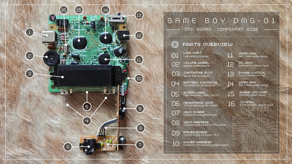
At the centre of the machine is a single chip Nintendo had Sharp build for it: the LR35902, whose processor core is usually called the SM83. It is an 8-bit processor, meaning it works on eight bits (one byte) at a time, and it runs at a modest 4.194304 megahertz. By 1989 standards that was already slow, but it was cheap, sipped power and generated little heat, exactly the trade Nintendo wanted for a battery handheld.
Its instruction set is a hybrid. It borrows ideas from two famous 1970s processors, the Intel 8080 and the Zilog Z80, but it is neither of them: Nintendo and Sharp kept the instructions that were useful, dropped the ones that were not, and added a few of their own. The result is a chip that assembly programmers describe as Z80-like without being a Z80. Crucially, the LR35902 is more than a processor.

Onto the same piece of silicon Sharp integrated the sound hardware, a timer, the serial controller for the link port, a small direct-memory-access engine for moving sprite data, and the basic logic that ties memory together. Packing all of that into one chip is a big reason the whole console fits on one small board.
Black blobs and a copper lid
Look closely at the board and you will not see neat rectangular chips with legs where the processor and memory should be. Instead there are smooth black blobs. This is chip-on-board construction, often called glob-top: the bare silicon die is glued straight onto the board, its microscopic pads are wired to the copper tracks, and the whole thing is sealed under a drop of black epoxy to protect it. It is cheaper and more compact than putting each die in its own plastic or ceramic package, and it is why a Game Boy board looks strangely bare.

Because those dies sit exposed under only a thin epoxy cap, the copper plate described in Part 1 lies across them as a heat spreader, pulling warmth away so nothing runs hot. The board itself is stamped with its identity, typically DMG-CPU followed by a revision number and a 1989 Nintendo marking, next to a small inspection stamp from the factory. Nintendo quietly revised this board several times across the Game Boy's long life, which is why two grey bricks opened side by side can carry slightly different board numbers.
Memory: eight kilobytes, twice over
The Game Boy carries two separate banks of memory, each eight kilobytes. The first is the work RAM: fast scratch space where the running game keeps its variables, its map of the moment, the positions of characters and everything else it needs to change from frame to frame. The second is the video RAM, a dedicated store that feeds the screen.
That video memory holds the raw material of every Game Boy image: small 8-by-8 pixel tiles, and the maps that say which tile goes where, plus the data for the moving sprites. The processor writes into video RAM and the display hardware reads it out, line by line, to build the picture. Sixteen kilobytes in total sounds almost impossibly small, and it is, but it was enough because the heavy lifting lived elsewhere: the real bulk of each game, its levels, graphics and music, rode on the cartridge, which the next point explains.
The heartbeat: a 4.194304 MHz crystal
Near the processor sits a tiny metal can or cylinder: a quartz crystal. When a voltage is applied, the quartz vibrates at an extremely precise frequency, and that vibration is the clock that paces the entire machine. The Game Boy's crystal runs at 4.194304 megahertz, and every other rhythm in the console, the speed of the processor, the timing of each screen refresh, the pitch of the sound channels, is derived by dividing that one number down. The oddly specific figure is chosen precisely because it divides so cleanly into the timings the hardware needs.
The cartridge connector
At the top edge of the board, a row of contacts forms the cartridge connector. This is where the console's small built-in memory meets the game. A Game Boy cartridge is not just read-only storage: beyond its ROM, many carts carry extra RAM, a small battery to keep saved games alive, and a chip called a Memory Bank Controller. Because the 8-bit processor can only address a limited amount of memory at once, the Bank Controller lets a large game swap, or page, different chunks of its ROM into view on demand, which is how cartridges grew far bigger than the console alone could ever address. The cartridge is a whole topic in its own right, and the series returns to it.
Everything else on the board
The same board carries the quieter supporting cast. The serial controller drives the link port for connecting two consoles. A socket takes the six volts coming in, whether from the batteries or an external adaptor, which the separate power board then converts into the voltages the logic actually uses. The power switch feeds that supply in. And a flat ribbon cable runs from this board to the screen-and-button board on the front half of the console, carrying both the picture data to the display and the button presses back. Those two boards, and how the picture is actually made, are where the next parts go.
Specifications at a glance
Property | Specification |
|---|---|
Processor | Sharp LR35902 (core nicknamed SM83) |
Architecture | 8-bit |
Clock speed | 4.194304 MHz |
Instruction set | Hybrid of Intel 8080 and Zilog Z80 |
Integrated on-chip | CPU, PPU, sound, timer, serial, DMA |
Work RAM (WRAM) | 8 KB |
Video RAM (VRAM) | 8 KB |
Chip packaging | Chip-on-board (glob-top epoxy) |
Clock source | 4.194304 MHz quartz crystal |
Board marking | DMG-CPU (+ revision), (c) 1989 Nintendo |
Cartridge interface | ROM, optional RAM / battery / MBC |
The Series
Overview · Part 1: The Shell, Buttons and Controls · Part 2: The Main Board and the Sharp Processor (you are here) · Part 3: The Screen · Part 4: Sound · Part 5: Power · Part 6: Connectivity and the Link Port



Comments